An independent CFD code for switching arc simulation.
A failed interruption test costs a high-power laboratory slot and weeks of project delay. NAVARC simulates the milliseconds that decide the outcome — arc, gas blast, nozzle ablation, moving contacts — before the hardware exists.
The mark above is not an illustration: it is six isotherms of a computed arc temperature field, extracted by marching squares. The two hottest levels carry the warm colour — on this site, colour only ever marks data.
Reference result — a 12 ms self-blast interruption duty
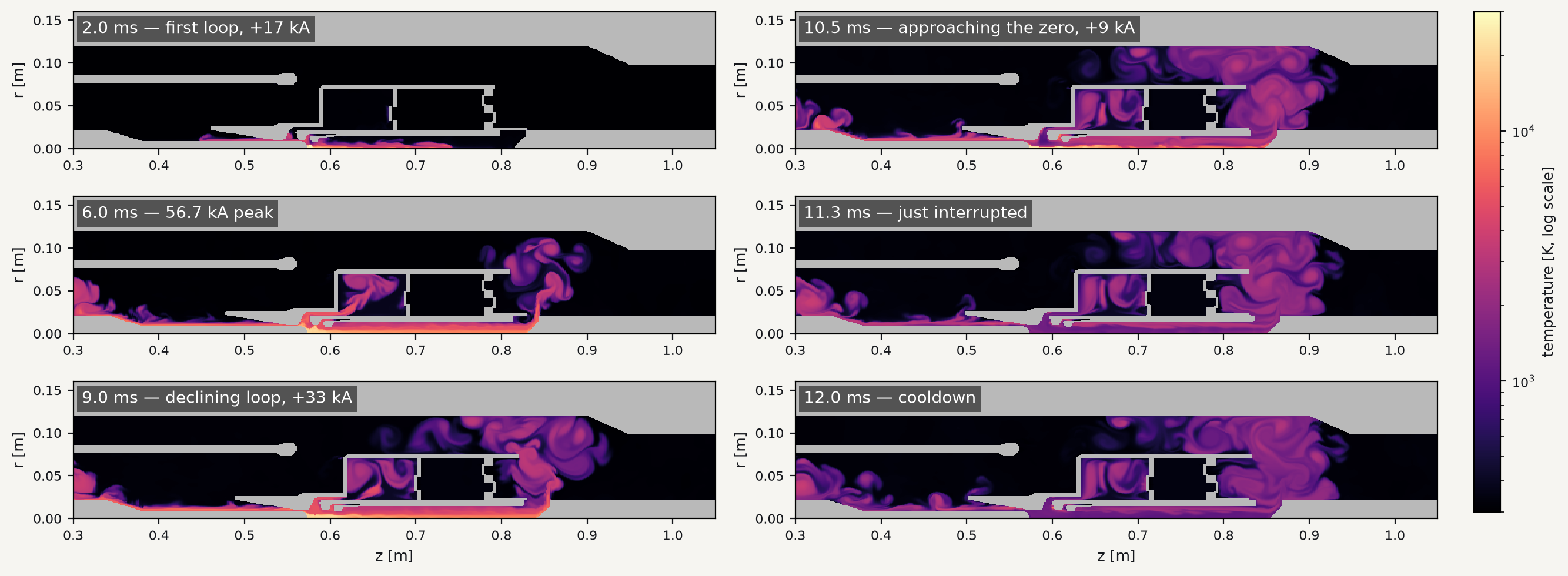
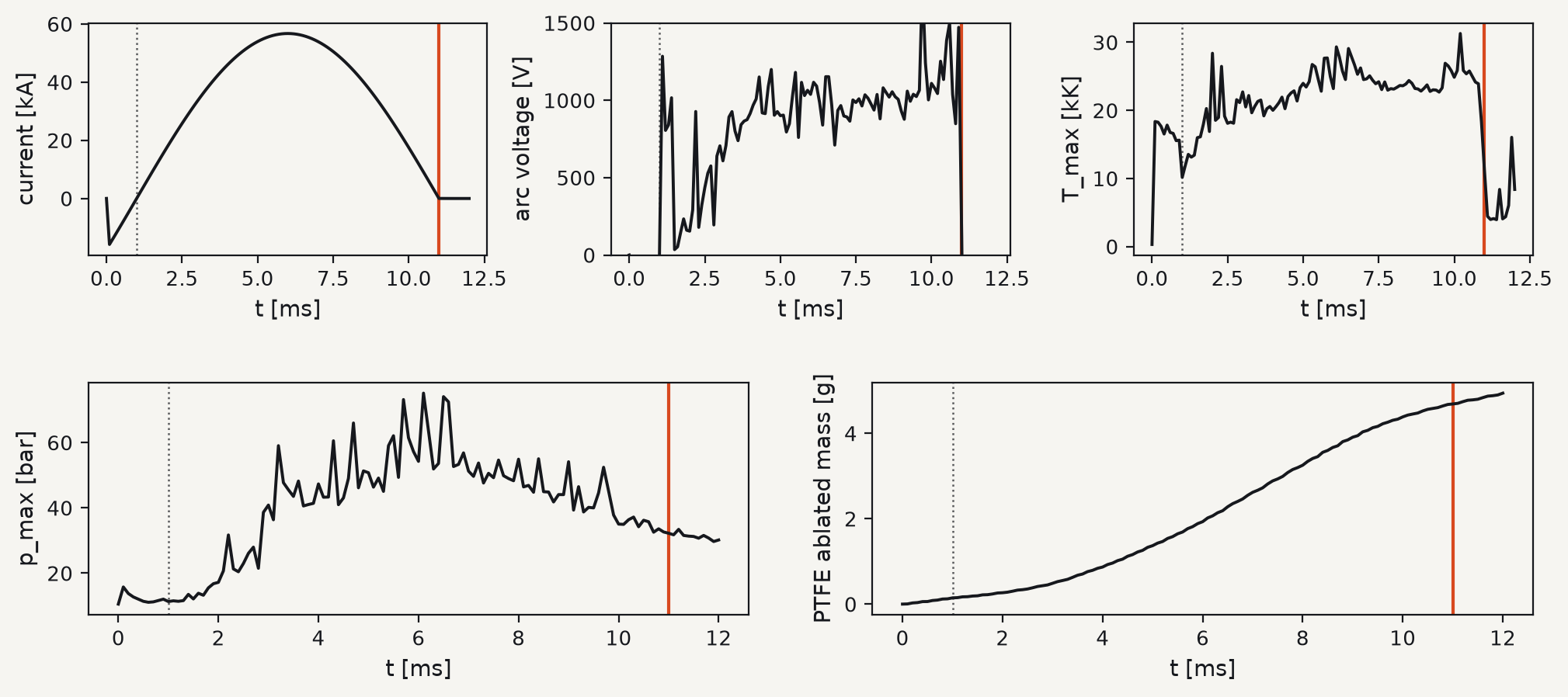
A complete breaker duty in one continuous calculation: a self-blast breaker filled with CO₂ + 20% O₂ (an SF₆-free quenching gas) at 8 bar, compression volume pre-charged to 10.5 bar, with PTFE nozzle ablation, three force-coupled valves and all arc models active. The arc rides the 1 ms current zero unaided through a full 56.7 kA loop, interrupts cleanly at the 11 ms zero, withstands the recovery voltage, and the calculation verifies a further millisecond of cooldown.
What that buys in practice
Design findings before hardware
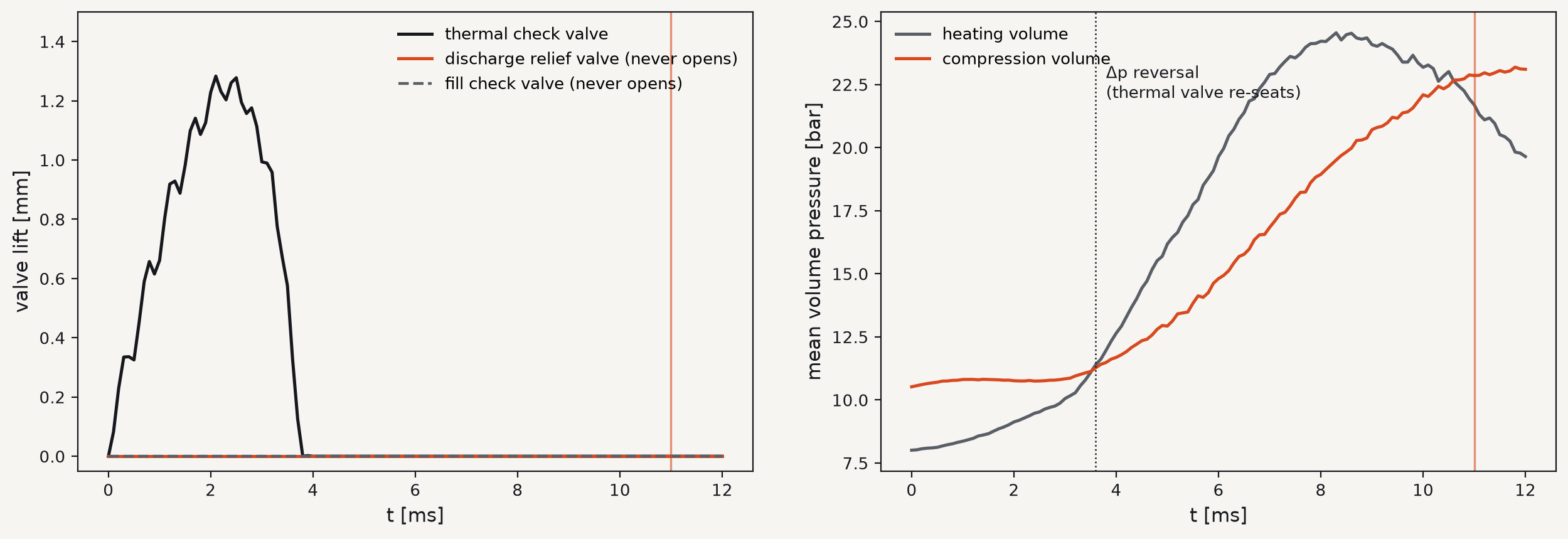
In the featured self-blast configuration, the calculation showed that a check valve backed by its support has unequal wetted areas front and back — it needs about 23 % overpressure to open, exactly as the real part would; that number now sets the pre-charge. An earlier relief-valve preload would never have cracked at all: the wetted-area force balance surfaced it, and the valve was retuned before any hardware existed.
Overnight design iterations
The full 12 ms interruption duty runs in roughly 12 h on a 4-core laptop — one design variant per night, no cluster, no licence server. A geometry change is a re-export from CAD, not a new meshing project.
What the code models
Compressible real-gas flow
2D axisymmetric Navier–Stokes with real-gas thermodynamics for SF₆, CO₂/O₂, N₂, air and C₂F₄ up to 100 kK — computed by an in-house 21-species equilibrium property pipeline (composition, transport, radiation), validated point-by-point against published tables.
Arc electrical model
Imposed current waveform, conductance-sliced arc column, series arc voltage, and an extinction / re-ignition model that mirrors how a real breaker recovers voltage at current zero.
Radiation & self-pinch
Net-emission-coefficient radiation with re-absorption in the cooler fringe and at walls — occlusion-aware — plus the magnetic self-pinch force of the column.
PTFE nozzle ablation
Wall heat flux drives self-limiting vapour blow-off; the vapour is injected hot with its mass, momentum and enthalpy, and blends into the gas as a fully composition-aware C₂F₄ species — including its exothermic oxidation in CO₂/O₂.
Moving & eroding geometry
Contacts and nozzles move on a fixed Cartesian grid with cut-cell embedded boundaries — no remeshing as parts translate or walls recede. Geometry comes straight from CAD assemblies.
Force-coupled valves
Spring-loaded and free check valves as 1-DOF bodies driven by the pressure integrated over their actual wetted faces — including valves that ride on moving carriers.
Built like an instrument
NAVARC is written in Rust — memory-safe by construction, with a zero-unsafe policy and a deliberately small dependency footprint (five runtime libraries; no legacy black box, no licence server). Finite-volume HLLC fluxes, second-order MUSCL reconstruction and SSP-RK3 time integration, with adaptive mesh refinement, SIMD kernels and multi-core parallelism where it counts.
Mass, momentum and energy are conserved to machine precision — including across refinement boundaries and moving walls — and every numerical scheme is guarded by property tests on its conservation invariants: 489 automated tests in the current build. Runs are checkpointed and restartable; every output is plain VTU/CSV, readable in ParaView or any tool you already use.
Verification
Every building block is verified against analytic solutions and published benchmarks, with exact conservation as the standing requirement. Representative results:
| What was tested | Result |
|---|---|
| Shock-tube (Sod) density accuracy | ≈ 1.4 % L2 error |
| Piston-driven pressure rise vs acoustic prediction | within 0.5 % |
| Viscous shear decay vs analytic solution | within 0.8 % |
| Closed-box mass drift over 500 steps | ≈ 2×10⁻¹⁴ |
| Two-level mass & energy conservation across refinement | ≈ 10⁻¹⁷ |
| PTFE ablation mass balance (solid removed = vapour injected) | machine precision |
| Arc source energy-balance closure (Joule + radiation) | ≈ 10⁻¹² |
| Gas property data vs published CO₂ tables and Saha checks | 20/20 anchor checks |
Where it stands — stated plainly
Simulation earns trust by declaring its own boundaries. The current build:
- 2D axisymmetric — no kink or azimuthally asymmetric arc motion.
- Local thermodynamic equilibrium composition; no electrode-sheath physics (the standard assumption for this class of circuit-breaker CFD).
- Laminar — no turbulence model, a deliberate choice consistent with most published circuit-breaker CFD.
- Imposed current waveform, with the network represented by a recovery-voltage ceiling at interruption.
- Correlation-based transport and radiation data, with quantified uncertainty (tens of percent near the transport peaks; a factor 2–3 on net emission — typical of the method).
- Verified to date against analytic solutions and published benchmarks; quantitative validation against test measurements is the next step — and an open invitation to laboratories holding pressure and arc-voltage records.
The workbench
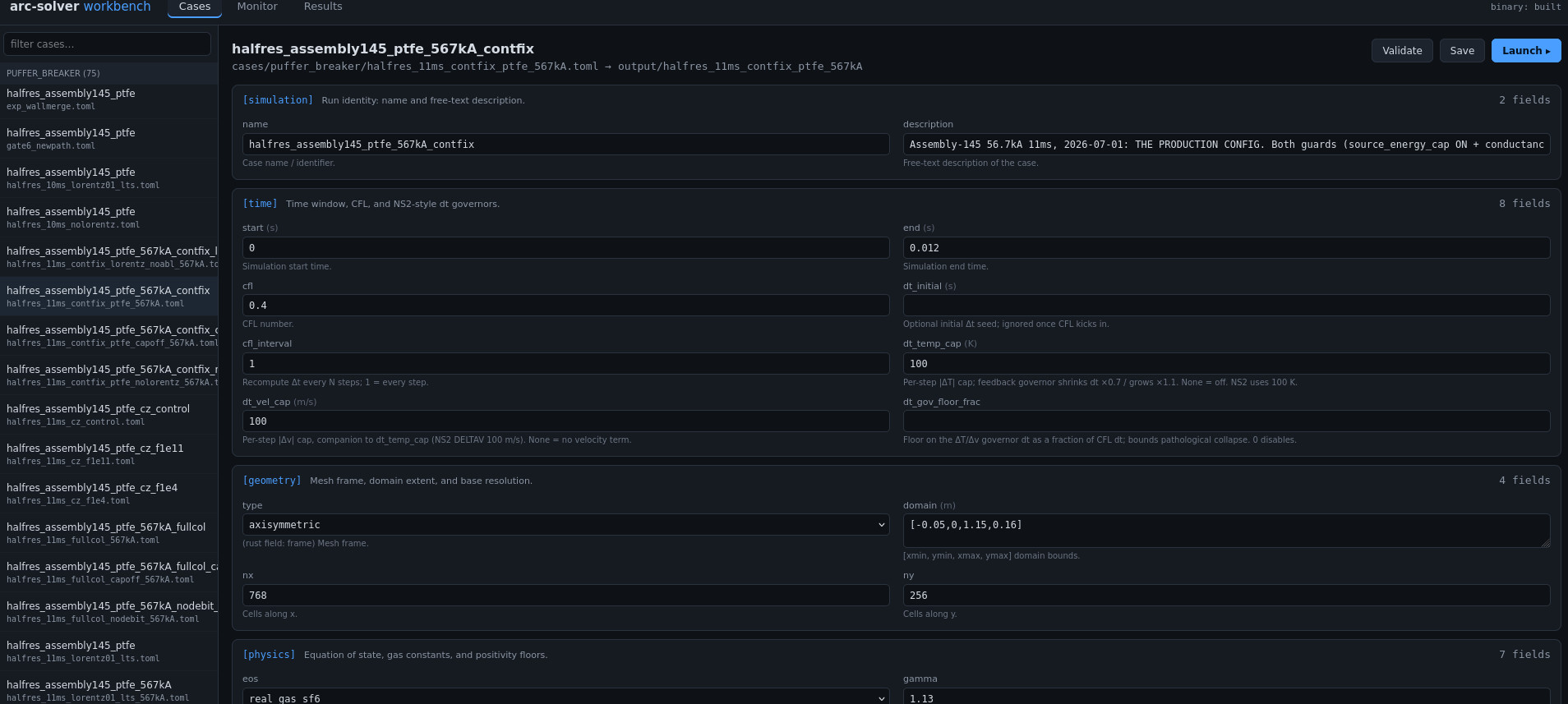
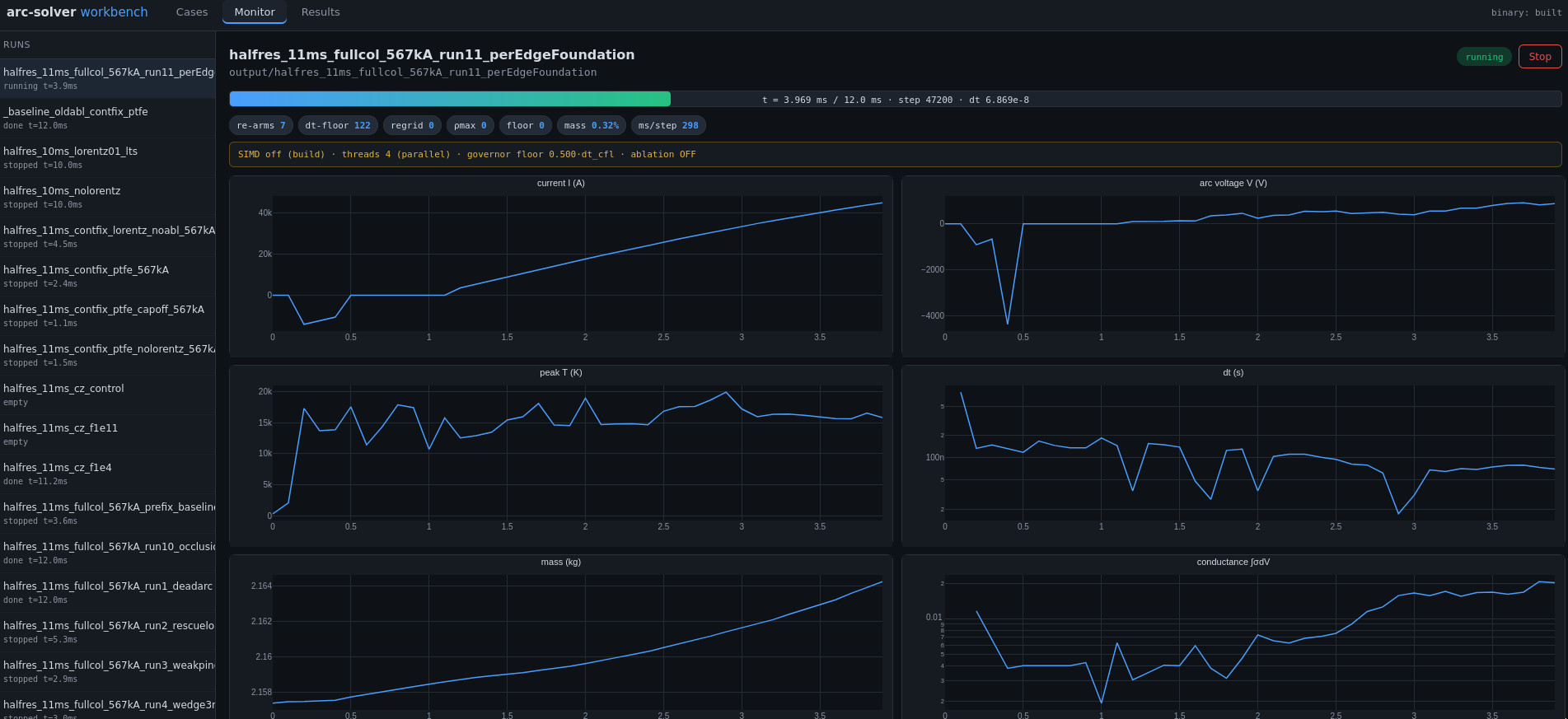
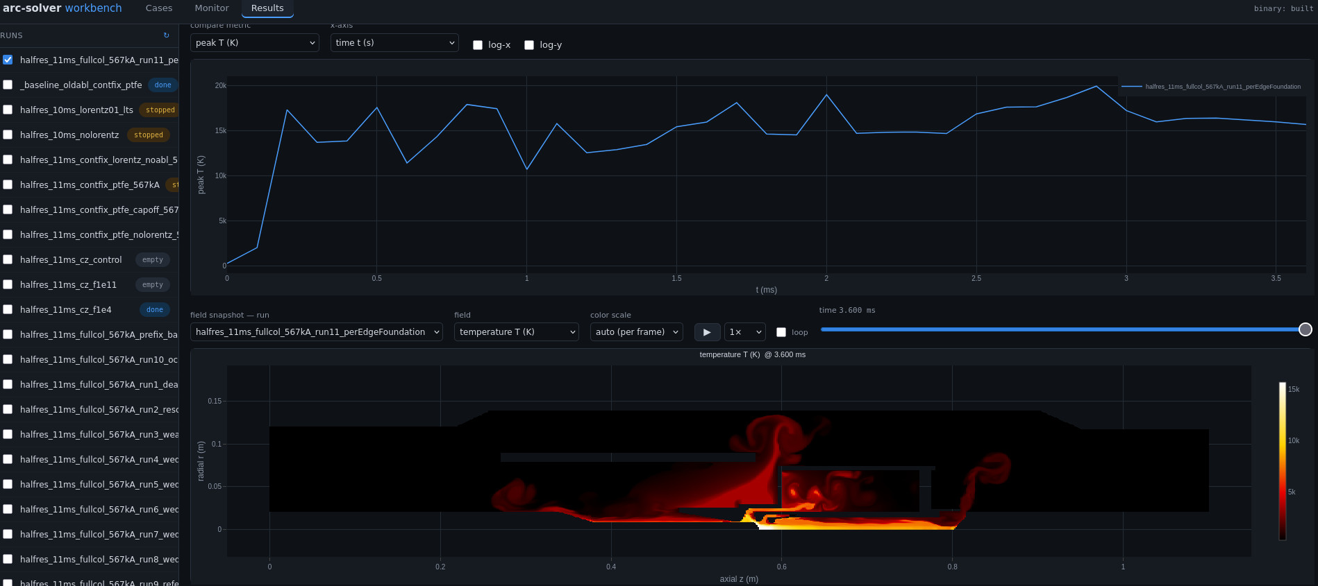
Cases are set up in a typed, schema-checked browser workbench — every parameter documented in place, validated before launch. Runs report live electrical and thermal telemetry, and results are browsed as field snapshots and multi-run comparisons.
Behind the code
NAVARC is developed by Karim Bousoltane — twenty years of high-voltage circuit-breaker development, from arc physics and interruption testing to R&D leadership, across major equipment manufacturers. The solver is the working instrument of an independent consulting practice: arc simulation studies, interruption-performance assessment, and expert support to breaker development teams.
The name reads Navier + arc: the equations, and the object they serve.
Ways of working
- Simulation studies on your geometry — CAD in, quantified interruption behaviour out.
- Development support — nozzle and chamber design, gas choice (SF₆ and SF₆-alternatives), test preparation and failure analysis.
- Independent expert review — second opinion on designs, simulations and test results.
Contact
The most useful first exchange is a concrete case: a geometry, a gas, a test that behaved unexpectedly. Confidential by default.
Karim Bousoltane · Lyon area, France · Interventions on site or remote, English and French.